# 1. Open Headset Interconnect Standard
* Open: Any individual or company may make devices compliant with this standard, with no obligation.
* Headset: Describes the signaling commonly found between a user and a radio: Microphone, Headphones, and Push To Talk.
* Interconnect: Describes both the physical and electrical connection of those signals between the user and radio.
* Standard: Devices built to this standard will work with other devices built to the same standard.
## 1.1. Introduction
There are so many different connections for microphone, headphone, and PTT that it is improbable you can take your preferred headset and connect it to any radio without a conversion device, and adapter. In this case, you need a full-mesh of adapters to go from every headset type to every radio type: O(N^2) adapters.
With the Open Headset Interconnect Standard, or OHIS, one can now build/purchase only one simple and inexpensive adapter for each device, and achieve full interoperability with only O(N) adapters.
This standard builds on the work done by Tom Tengdin [WB9VXY](https://www.qrz.com/db/WB9VXY), with his [Proposed ARES Standard Headset](http://www.sloecc.org/headsets/proposal_ares_standard_headset.pdf). This standard is different than his proposal in a few places to make it more generalized, and provides more detail and clarity around several points.
## 1.2. Table Of Contents
- [1. Open Headset Interconnect Standard](#1-open-headset-interconnect-standard)
- [1.1. Introduction](#11-introduction)
- [1.2. Table Of Contents](#12-table-of-contents)
- [2. Document History](#2-document-history)
- [3. TL,DR: Summary Technical Definition of the Standard](#3-tldr-summary-technical-definition-of-the-standard)
- [4. Why? What problems does this standard address?](#4-why-what-problems-does-this-standard-address)
- [4.1. Device Portability](#41-device-portability)
- [4.1.1. Existing Standards in Ham Radio](#411-existing-standards-in-ham-radio)
- [4.1.2. No such standard for the User/Radio interface](#412-no-such-standard-for-the-userradio-interface)
- [4.1.3. Non-OHIS Adapters](#413-non-ohis-adapters)
- [4.1.4. OHIS Adapters](#414-ohis-adapters)
- [4.2. Add-On Device Simplification](#42-add-on-device-simplification)
- [4.2.1. Add-Ons between the User and Radio](#421-add-ons-between-the-user-and-radio)
- [4.2.2. Complexity of Working With All Electrical and Physical Options](#422-complexity-of-working-with-all-electrical-and-physical-options)
- [4.2.3. OHIS as a Middle-Ware Standard](#423-ohis-as-a-middle-ware-standard)
- [5. Standard Details](#5-standard-details)
- [5.1. Architecture](#51-architecture)
- [5.1.1. User vs Radio](#511-user-vs-radio)
- [5.2. Physical](#52-physical)
- [5.2.1. Connector](#521-connector)
- [5.2.2. Cables](#522-cables)
- [5.2.3. Shielded Cables](#523-shielded-cables)
- [5.2.4. Sockets or Pigtails?](#524-sockets-or-pigtails)
- [5.3. Electrical](#53-electrical)
- [5.3.1. Microphone](#531-microphone)
- [5.3.1.1. Dynamic Microphones](#5311-dynamic-microphones)
- [5.3.1.2. Carbon (Equivalent) Microphones](#5312-carbon-equivalent-microphones)
- [5.3.2. Headphone](#532-headphone)
- [5.3.2.1. Speaker Level](#5321-speaker-level)
- [5.3.3. Power](#533-power)
- [5.3.4. PTT](#534-ptt)
- [6. Contact and Contribution to the OHIS](#6-contact-and-contribution-to-the-ohis)
- [6.1. Contributors](#61-contributors)
- [7. Appendix](#7-appendix)
- [7.1. Dynamic Microphone Preamp](#71-dynamic-microphone-preamp)
# 2. Document History
* 2022-08-26, v0.1, Work In Progress.
# 3. TL,DR: Summary Technical Definition of the Standard
A quick summary of the physical and electrical standard follows. If you have any questions, please see the [Standard Details](#5-standard-details) section below. Similarly, if there are any disagreements, the [Standard Details](#5-standard-details) section is authoritative.
There are two participants:
* User: Describes the "headset" side of the interconnect. Consumes the Headphone signal, generates the Microphone signal, and will trigger Push To Talk (PTT). Optionally uses the Vcc provided by the Radio side.
* Radio: Describes the device the "headset" connects to. Generates the Headphone signal, consumes the Microphone and PTT signals, and provides power to Vcc.
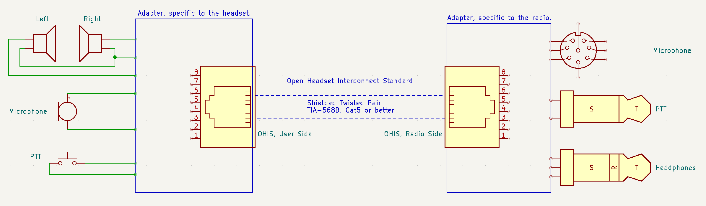
OHIS us an 8P8C Modular connector (commonly ([but incorrectly](https://en.wikipedia.org/wiki/Modular_connector#8P8C)) known as "RJ-45"), using TIA-568B wiring, shielded cable preferred but not required.
| Pin | Direction | Description |
|---|---|---|
| 1 | User <-- Radio | Vcc Power. Typically 5vDC, 200mA. 3.3vDC is acceptable. Fused or current limited. |
| 2 | User --> Radio | Push To Talk. User pulls to Power Ground. Radio may pull-up to no more than Vcc. |
| 3 | Common | Microphone Ground |
| 4 | User <-- Radio | Headphone Left Audio |
| 5 | Common | Headphone Ground |
| 6 | User --> Radio | Microphone audio, Electret (DC bias provided by Radio on this pin) |
| 7 | Common | Power/PTT Ground |
| 8 | User <-- Radio | Headphone Right Audio |
**Microphone:** The Microphone signal is a typical Electret microphone signal: 5vDC bias provided by the radio to power the microphone element, via 2.2k ohm resistor. Dynamic microphone elements will require about 10 to 15db of amplification. This standard also provides a simple 5 component microphone pre-amp, powered by this 5vDC bias, to bring a Dynamic microphone element up to Electret signal levels.
**Headphones:** The Headphones signals are typical 16 to 64ohm headphones, about 1v RMS at full volume. If the source is mono, it must drive both Left and Right signals and can just tie them in parallel (assuming the driver can handle the lower impedance.) If the destination is mono, it can choose to either use only the Left audio, or to mix Left and Right together.
**Power:** The Radio must provide at least 200mA of 5vDC (where possible, but as low as 3.2vDC is acceptable if not), for the User device to run amplifiers, DTMF/tone generators, signal processing, etc.
**PTT:** The User triggers PTT using a simple contact closure to Power Ground. The Radio side must not pull it up to any higher than Vcc.
**GROUNDS!** Where possible, the User devices will keep the three Grounds separate: 1) Mic and Mic Ground, 2) Headphones Left/Right and Headphone Ground, and 3) Vcc/PTT and Power Ground. This will allow for the best audio quality, least cross-talk, fewest ground loops, etc.
But in some cases, this isn't possible. eg: A 4-pin TRRS Headset connector which shares a common ground between the Mic and Headphones. **THE RADIO DEVICE MUST SUPPORT THIS.** The Radio MUST NOT require anything other than "Ground" on the Mic or Headphone Ground pins. That is, no push-pull on the Headphones, no DC bias'd Mic Ground, etc.
# 4. Why? What problems does this standard address?
## 4.1. Device Portability
The Open Headset Interconnect Standard allows a User to take their OHIS compliant Headset/Adapter to any OHIS compliant Radio/Adapter.
### 4.1.1. Existing Standards in Ham Radio
There are several physical and electrical standards used in Amateur Radio, such as:
* Power: 13.8vDC +/- 15%. Anderson Powerpoles are the ARES standard for delivering this power. (Citation needed.) Before that, there were several physical connectors: "T blade" commonly used in mobile VHF/UHF radios, "6-pin Molex" (but not really a Molex) connector used on desktop HF radios, etc. But they all carried the same 13.8vDC power.
* RF: 50ohm unbalanced coax with one of several standard connectors: SO-239/PL-259, Type N, BNC, SMA, etc. Because of the common electrical standard, the connectors are easy to adapt between.
In each case, there's one electrical standard, and at least one physical standard. But because of the electrical standard, converting between the physical standards is easy.
### 4.1.2. No such standard for the User/Radio interface
Such a standard doesn't exist between the User and the Radio, for either electrical or physical. Different electrical options include:
* Microphone: What type of mic element: dynamic, electret, or carbon? Balanced or unbalanced? Does it require a DC bias voltage, or will a DC bias voltage burn out the mic element?
* Headphones: Mono or stereo? Is it really a headphone level, or is it a speaker level? Ground referenced single ended, or push-pull?
* Push To Talk: Is it a GPIO style contact closure to ground, or does it key by grounding the Microphone element, passing microphone audio through the PTT switch (common on HTs.)
Physical options include:
* Microphone: 3.5mm TS, XLR, one of several different modular plugs (eg: 8P8C/RJ45, 6P6C/RJ6), or 4-pin/8-pin "round aviation" plugs? Which of the multiple pin-out options for the modular and 8-pin round connectors? What other signals are available on the mic connector?
* Headphone: 3.5mm or 1/4"? TS or TRS?
* PTT: Is it on its own connector, or part of the microphone connector? If its own, is it 3.5mm, 1/4", RCA? If 3.5mm or 1/4", is it TS, or TRS and shared with a morse key?
### 4.1.3. Non-OHIS Adapters
Making an adapter to go from one specific User interface not designed for the radio (such as an after-market headset) to one specific Radio is certainly possible. Some such adapters will be completely passive, just wires to change physical connectors. Others may require active electronics, such as amplifiers, which require power. But all this is possible. And in a situation with one User interface and one Radio, is the simplest option.
But if that User takes their preferred interface (their headset) to a different radio, such as an ARES EOC or a club Field Day event, and wants to connect it to a radio with a different electrical and/or physical interface, that user will need a different adapter.
### 4.1.4. OHIS Adapters
The Open Headset Interconnect Standard defines both an electrical and physical standard. Every User builds or buys an adapter to convert their preferred headset to the OHIS standard, and every Radio owner builds or buys an adapter to convert OHIS to their radio. The OHIS adapters stay with their devices. User devices can quickly connect and disconnect from Radio devices without concern for the electrical or physical characteristics. No adapter unique to the pairing of those two devices, headset and radio, is required.
## 4.2. Add-On Device Simplification
The Open Headset Interconnect Standard allows add-on devices designed to connect between the User and the Radio to be greatly simplified.
### 4.2.1. Add-Ons between the User and Radio
Consider as an example, a Headset Mixer Console: A User has at their operating position an HF radio for nets and rag-chewing, a VHF/UHF radio to listen to a local repeater, and maybe their computer they use to listen to music or watch videos. They have a single high quality headset they would like to use for all these purposes. They'd also like to monitor the repeater while using the computer, or working an HF net.
A device could be build that would mix the headphone/speaker audio from all these different devices, and send it to the headset. Similarly, the microphone from the headset could be split and sent to all devices. A single PTT button, foot switch, or similar, could be switched between the different radios.
### 4.2.2. Complexity of Working With All Electrical and Physical Options
To build this device to work with all electrical and physical options, on both the user and the radio side, adds a lot of complexity and cost to the device. Configuring the device for the correct headset/radio configuration as devices are added or removed is also complex, and risks damaging equipment if its done incorrectly.
### 4.2.3. OHIS as a Middle-Ware Standard
Moving the complexity of all the different options to adapters that stay with their respective device, and using OHIS in the middle, allows this Add-On device to be greatly simplified. It no longer has to support all available options, it only has to support OHIS. It trusts in the OHIS Adapters on the User and Radio side to do the device-specific part.
This simplifies the design, and lowers cost.
# 5. Standard Details
The following section describes the physical and electrical characteristics from the Open Headset Interconnect Standard.
## 5.1. Architecture
To explain the OHIS architecture, consider an example of connecting a headset to a radio. The headset has stereo headphones, a microphone, and a PTT button on the cord. The radio has an 8-pin microphone connector that includes the PTT signal, and a headphone connector. But the headset connectors are different than the radio connectors.
The User would build or buy an adapter to convert their headset connections (whatever they are) to OHIS User. This adapter is specific to this type of headset. This adapter stays with the headset forever.
The owner of the Radio would build or buy and adapter to convert their radio connections (whatever they are) to OHIS Radio. This adapter is specific to this type of radio. This adapter stays with the radio forever.
OHIS defines the connection between these two adapters:

It's possible (hopeful!) that devices will be built to use OHIS directly, not requiring any adapters.
### 5.1.1. User vs Radio
To further clarify the use of "User" and "Radio:"
* User Device: Commonly referred to as "the headset" in this document, but isn't necessarily an actual headset. Any device that consumes the Headphone signal from the Radio, and generates a Microhphone signal sent to the Radio, and is capable of triggering the PTT, is considered a User device. It could be a separate headphone, mic on a boom arm, and a foot switch. Or it could be a "speaker-mic" as commonly found on HTs.
* Radio Device: Again, this is not necessarily a Radio. Any device that consumes a Microphone signal and generates a Headphone signal, and (optionally) does something useful with the PTT signal, is considered a Radio device. It could be a computer audio interface, or a BlueTooth connection to a phone.
## 5.2. Physical
### 5.2.1. Connector
The connector is an 8P8C Modular connector, commonly ([but incorrectly](https://en.wikipedia.org/wiki/Modular_connector#8P8C)) referred to as an RJ-45.
### 5.2.2. Cables
The cables used must be wired as TIA-568B. Specifically, OHIS assumes wires are paired as described in TIA-568B: 1&2, 3&6, 4&5, 7&8. (TIA-568A also works for straight-through cables (pairs are on the same pins), but when pair colors are discussed in this document we will use TIA-568B colors.)
The above allows the use of common off-the-shelf "Ethernet" cables for use when connecting OHIS devices. Any category from Cat5 or above will work; OHIS has no high-speed requirements on the cable.
### 5.2.3. Shielded Cables
Shielded cables are preferred, but not required. Either whole-cable shields, like used in Cat5 STP, or per-pair shields, like used in Cat6A and above, will work. When per-pair shields are used, all shields are terminated together.
Shields Must be connected to Power Ground on the Radio side, and Must Not be connected at the User side (to prevent Ground loops. **TODO** Is this really the right thing to do?)
### 5.2.4. Sockets or Pigtails?
Both OHIS User and Radio May use 8P8C Sockets, which would use a "standard Ethernet cable" to connect the two.
An OHIS User device May incorporate the cable directly into the device, creating a "pig tail" that connects directly to OHIS Radio device.
OHIS Radio devices Must be a socket, and May Not have integrated cables.
## 5.3. Electrical
### 5.3.1. Microphone
The Microphone signal in OHIS is a conventional Electret Microphone element, as commonly used in mobiles, HTs, computers, and phones. That is:
* About 1kOhm load impedance.
* About -40dBm signal strength.
* The Radio side provides 3.3vDC to 12vDC Bias voltage through 2.2k ohm impedance.
* This DC bias voltage should be as free from noise as possible. Any noise on this supply will conduct directly to the microphone input on the radio.
The Microphone Signals are carried on Pins 6 (Microphone) and 3 (Microphone Ground), which are the Green pair in TIA-568B wiring.
Microphone Ground should be kept as separate as possible (not tied to Power or Headphone Grounds unless absolutely necessary), allowing Microphone signal return currents, and ONLY the Microphone signal return currents, to be seen by the Microphone receiver on the Radio side. Ideally, the Microphone receiver circuit treats the Microphone pair as a balanced signal to reject common mode current noise picked up by the Microphone cables.
This may not always be possible (eg: a 4 pin TRRS headset with a shared Mic and Headphone Ground). In these situations, it is acceptable to tie the two grounds together. But this should only be done if absolutely necessary.
#### 5.3.1.1. Dynamic Microphones
Dynamic Microphone elements, as commonly used with HF radios and professional audio, will need to be amplified by about 10 to 15dB to reach this level. The DC Bias also needs to be removed.
A simple 5 component circuit to do this (amplification and bias removal) is available as part of this standard, free for all to use without obligation. See [Appendix, section 7.1](#71-dynamic-microphone-preamp) for this circuit.
Similarly, a Radio expecting a dynamic microphone signal will need about 10 to 15dB of attenuation, and cannot back-feed a DC bias into the radio. A simple 10:1 voltage divider and series DC blocking capacitor can accomplish this. **TODO** Document this here? Appendix?
#### 5.3.1.2. Carbon (Equivalent) Microphones
Carbon, or Carbon Equivalent, microphones, as commonly used with aviation headsets and telephone handsets, will need about 20dB of attenuation to reach this level.
This can be accomplished with a simple 100:1 voltage divider. But the DC bias voltage needs to be passed through, or re-generated from Vcc power. **TODO** Document this here? Appendix?
Similarly a Radio expecting a Carbon (Equivalent) signal will need about 20dB of amplification. **TODO** Document this here? Appendix?
### 5.3.2. Headphone
The Headphone signal in OHIS is a conventional headphone style signal, as used pretty much everywhere. That is:
* Commonly between 8 and 64 ohms load impedance. Some less common headphones can be as high as 300 ohms.
* About 10dBm to 20dBm (10mW to 100mW) of power.
* Ground referenced single ended audio. No DC offset, and no push-pull.
* Stereo signals must share a common return path Ground.
The Headphone Signals are carried on Pins 4 (Left), 8 (Right), and 5 (Headphone Ground). Left and Headphone Ground are on the Blue pair, and Right is paired with Power Ground on the Brown pair (TIA-568B wiring.)
Similar to the Microphone Ground, the Headphone Ground should be kept as separate as possible, preventing the Headphone return currents from impacting the Microphone signal.
This may not always be possible (eg: a 4 pin TRRS headset with a shared Mic and Headphone Ground). In these situations, it is acceptable to tie the two grounds together. But this should only be done if absolutely necessary.
#### 5.3.2.1. Speaker Level
Speaker level audio signals are commonly between 4 and 8ohms, and between 1W and 10W. Speaker amplifiers also often drive both sides of a speaker signal (for increased power output), meaning that the signal is NOT ground referenced.
When taking a Speaker level signal as an input on the Radio side, it's best to pad it down by 20dB (10:1 ratio voltage divider), then isolate it using a 1:1 audio transformer.
Generating a Speaker level signal on the User side is beyond the scope of this document. The Headphone signal can be used as a Line Level signal to feed a conventional speaker amplifier.
### 5.3.3. Power
Vcc Power is on Pin 1, paired with PTT on the Orange pair, and Power Ground is on Pin 7, paired with Headphone Right audio on the Brown pair (TIA-568B wiring.)
The Radio side provides Vcc = 5vDC power, and supply at least 200mA. This line must survive accidental shorts to ground, either with a resettable fuse or other current limiter. This line should be free from AC ripple (**TODO** Quantify this. 10mV or less?)
Over-voltage by 10% (5.5vDC) is acceptable. If the power source feeding the Radio side of the OHIS adapter provides more than 5vDC, it must be regulated down to 5vDC.
In situations when the Radio side doesn't have 5vDC power, under-voltage as low as 3.0vDC (lower end of a single Li-Ion cell's voltage) is acceptable; there's no need to boost it up to 5vDC. But be aware that the lower voltage overhead may compromise performance of some OHIS User devices.
OHIS User devices Must work with 5vDC and consume no more than 200mA. OHIS User devices Should work with as little as 3.0vDC power if possible. For example, use a Vcc/2 voltage divider to generate BIAS voltages, rather than a fixed 2.5vDC.
### 5.3.4. PTT
PTT is on Pin 2, paired with Vcc on the Orange pair of TIA-568B wiring.
The User side triggers Push To Talk (PTT) by shorting the PTT signal to Power Ground. This can be a simple contact closure of a button or relay, or an active transistor driven pull-down to ground. The PTT line is a GPIO signal, no audio passes through the PTT signal. So extending PTT controls through long wires is acceptable. However, care should be taken to not pick up and conduct noise to the rest of the circuit.
# 6. Contact and Contribution to the OHIS
The Open Headset Interconnect Standard is sponsored and hosted by Halibut Electronics, Inc.
The official source for the Open Headset Interconnect Standard is: [https://github.com/Halibut-Electronics/Open-Headset-Interconnect-Standard](https://github.com/Halibut-Electronics/Open-Headset-Interconnect-Standard)
Provide feedback and suggestions through [GitHub Issues](https://github.com/Halibut-Electronics/Open-Headset-Interconnect-Standard/issues) on the Standard repository.
## 6.1. Contributors
* Mark Smith, N6MTS, SmittyHalibut on [GitHub](https://github.com/SmittyHalibut/) and [Twitter](https://twitter.com/Smittyhalibut), mark-ohis@electronics.halibut.com
* Tom T. Tengdin, WB9VXY, wb9vxy@arrl.net
# 7. Appendix
## 7.1. Dynamic Microphone Preamp
The two most common microphone element types used in ham radio are Dynamic and Electret. Since OHIS uses Electret level as it's standard, a common need is a Dynamic Microphone Preamp.
This simple design is included in the Standard for all to use with no obligation or concerns about IP.
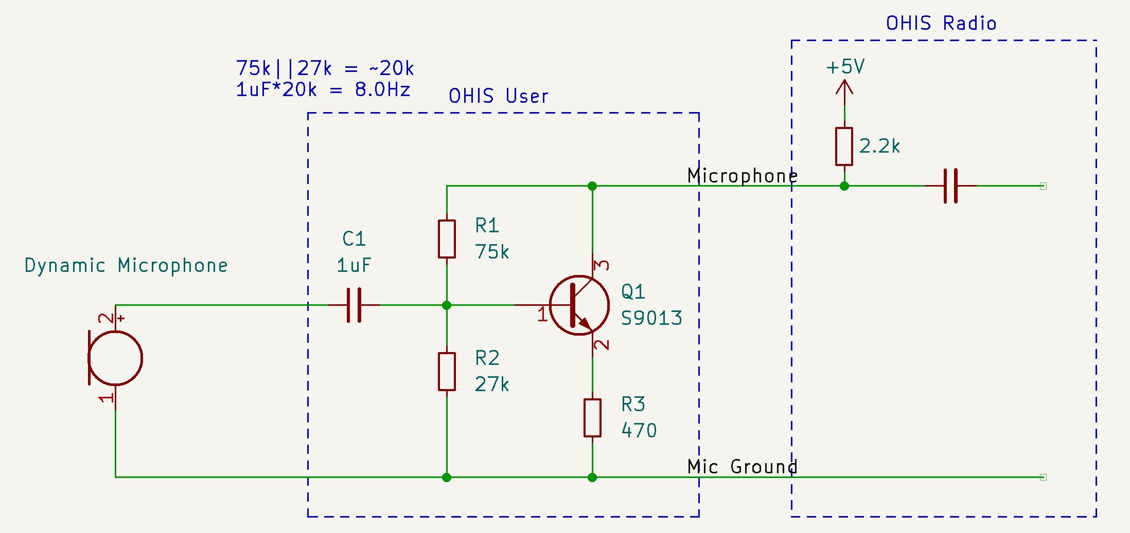
* C1: 1uF ceramic or other non-polarized capacitor. At least 6.3v rating.
* The low-end frequency response of the microphone can be adjusted by changing the value of C1. Frequency = 1/(2\*Pi\*R\*C). R is roughly 27k and 75k in parallel, or about 20k ohm. C is the value chosen for C1.
* 1uF into the ~20k ohm impedance of the amplifier rolls off at about 8Hz. Using a .1uF would roll off at 80Hz instead, eliminating some rumble and wind/handling noise.
* R1: 75k ohm resistor, at least 1/16W.
* R2: 27k ohm resistor, at least 1/16W.
* R3: 470 ohm resistor, at least 1/16W.
* Q1: S9013, or similar NPN BJT transistor.
* Tests were performed (by Mark Smith in 2022-08) using an S9013 transistor, but nearly any small signal NPN BJT should work. For example, a 2N3904 (through hole) or MMBT3904 (surface mount) should work equally well.
An example recording of audio through this microphone preamp design is [here](https://halibut-electronics.github.io/Open-Headset-Interconnect-Standard/2022-08-18%20First%20Test%20Of%205%20Component%20Preamp.mp3).
This circuit is only a slight modification of a conventional common emitter transistor amplifier, similar to what's analyzed [here](http://www.guitarscience.net/calcs/ce.htm). The difference being that we are using the 2.2k ohm resistor in the Radio side (upper right corner above) as the collector resistor. This means the top-side base resistor (R1 above) connects to the output, not to Vcc.
**TODO** Analyze this in Spice and quantify the actual impact of this. Testing suggests it works fine.
**TODO** Provide actual measurements.